
Appearance
Basler GigE Camera
This page provides instructions for setting up and using the Basler GigE camera within the platform. The Basler camera is an industry-standard, high-performance industrial camera that offers exceptional image quality and flexibility for computer vision applications.
Supported models
The only supported model is the Basler ace 2 a2A3840-13gcBAS.
💡 Tip
Currently, the only supported interface is GigE. USB3 connections are not supported.
Benefits and use cases
The Basler GigE camera is well-suited for a variety of use cases in computer vision, including:
High image quality: Captures uncompressed images, ensuring no loss of detail.
Industry standard: Widely used in industrial and research applications, ensuring reliability and compatibility.
Hardware trigger support: Allows precise frame capture timing for specific events.
Adjustable shutter speed: Offers precise control over exposure time in microsecond increments, allowing optimization for various lighting conditions and applications, such as capturing detailed images in high-speed industrial processes or low-light environments.
GigE interface: Enables high-speed data transfer over standard Ethernet connections.
Connect the Basler camera to the network
This section explains how to properly connect a Basler GigE camera to your network to ensure it works reliably with your system.
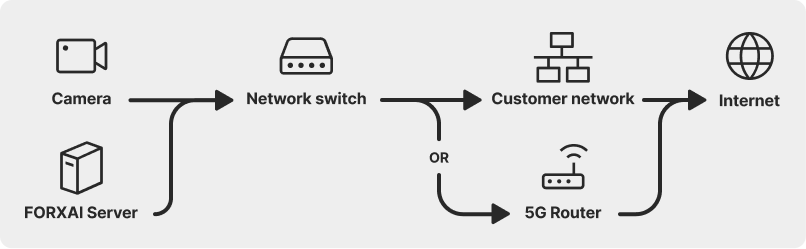
⚠️ Warning
Basler cameras cannot operate when connected through routers or VPNs. Their high-performance nature and reliance on the GigE Vision protocol require a direct, low-latency connection.
Why won't routers or VPNs work?
Increased latency
Routers introduce processing delays due to NAT (Network Address Translation), firewall checks, and packet handling. This added latency can disrupt real-time or near-real-time image capture and analysis.
VPNs further increase latency by encrypting and tunneling data, which can disrupt synchronization with other devices.
Bandwidth constraints
- Basler cameras generate high volumes of image data, which routers and VPNs are not optimized to handle. This can result in packet loss, reduced frame rates, or buffering issues.
Unpredictable network behavior
Routers can reorder or prioritize packets, interfering with the GigE Vision protocol used by Basler cameras.
VPNs depend on public internet infrastructure, leading to variability in packet delivery and bandwidth availability.
Protocol limitations
- The GigE Vision protocol is designed for local subnets and requires features like Jumbo Frames, which routers and VPNs may not support or block entirely.
Synchronization and triggering
- Time-sensitive processes, such as hardware triggering and synchronization with other devices, can be disrupted by the variable delays introduced by routers and VPNs.
When setting up the Basler GigE camera, it's important to establish a stable connection to your system. Follow these guidelines to ensure proper connectivity:
Direct connection to a server or industrial switch
We recommend connecting the camera directly to your server or a high-quality industrial-grade Gigabit Ethernet network switch. Avoid using standard consumer-grade routers or switches, as they may introduce latency or bandwidth limitations unsuitable for high-performance applications.
Power over Ethernet (PoE) support
If your Basler camera supports Power over Ethernet (PoE), ensure that your network switch or Ethernet port supports PoE to power the device without an external adapter.
IP address configuration
Configuring the address on the camera is done through the Basler pylon Viewer.
💡 Tip
The Basler camera supports only one active connection at a time. You cannot connect to or configure the camera in the pylon Viewer while a deployment is running, and similarly, you cannot run a deployment while the camera is connected to the pylon Viewer.
Assigning a static IP address to the camera is recommended as a best practice. This ensures that the camera's address remains fixed, simplifying system integration and troubleshooting. If a static IP is not feasible, the camera can be assigned an IP address using a customer-managed DHCP server, provided the IP remains reserved for the camera to prevent changes during operation.
⚠️ Warning
Dynamic IP assignment is not supported.
Gigabit ethernet cable Use a high-quality Gigabit ethernet cable (Cat5e or Cat6) to ensure optimal data transfer speeds and avoid signal degradation.
Configure the server IP address
To enable communication between the server and the camera, you must add the server IP address to the server’s configuration file.
Follow these steps:
Connect to the server using a terminal application:
bashssh vasadmin@x.x.x.x💡 Tip
- Replace
x.x.x.xwith the server IP address. - If you are on Windows, you can use tools like WSL, Putty, or Windows Powershell.
- Replace
Enter the password
vasadminwhen prompted.Switch to root privileges:
bashsudo -iSwitch to the following folder:
bashcd /srv/compose/shinanoEdit the shinano.env file using the vi editor:
bashvi shinano.envPress
Ito edit the file as follows:- Use arrow keys to navigate to the line that says
#GIGE_HOST.

Unedited line - Use arrow keys to navigate to the line that says
Remove the hash sign #. 3. Replace the
<your-physical-machine-IP>with the server IP address.
><figure style=" flex: 1; text-align: center; display: flex; flex-direction: column; align-items: center; " > <img src="/public/gigeHost2.png" alt="Putty SSH error" style=" border: 1px solid lightgray; border-radius: 8px; width: 30%; height: auto; " > <figcaption style="margin-top: 5px">Edited line example</figcaption> </figure></your-physical-machine-IP- Type
:xand press Enter to save and exit.
- Type
In the Terminal, use the following command to relaunch the application with the changes:
bashdocker compose up -d
Add the Basler camera to the platform
To add a Basler camera to the system, follow these steps:
Go to Devices and click Add device.
Select the Basler™ GigE Camera device type.
Fill in the remaining fields as follows:
Device name
A user-defined label for the camera.
IP address
The unique IP address of the camera.
How do I find the camera IP address?
To find the camera IP address, **follow these steps**: 1. Make sure the camera is connected to the network.Connect your PC to the same network as the camera.
Open the pylon Viewer.
Find your camera in the top left section and hover your mouse over it.
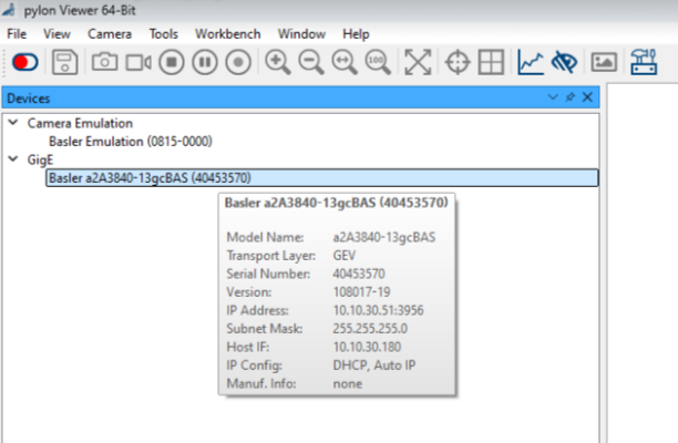
The address can be found next to the IP Address label.
Image queue size
Defines the number of images the camera can store in its buffer before processing. A larger queue size may be useful in high-frame-rate scenarios to avoid data loss.
Pixel format
• Mono8: Captures grayscale images with 8-bit depth, suitable for applications requiring high contrast.
• BGR8: Captures color images with 8-bit depth for each color channel, ideal for applications needing detailed color information.
Acquisition mode
• Continuous: The camera sends every frame it captures in real time.
• Hardware triggered: The camera waits for external trigger signals to capture frames.
Hardware trigger source (only applies to Hardware Triggered Acquisition mode)
Specifies the source of the hardware trigger signal. Refer to the Hardware trigger setup procedure.
Click Add to save the device.
Setting up a hardware trigger
This section explains how to configure a hardware trigger for Basler ace 2 cameras.
What is a hardware trigger?
A hardware trigger is an external signal used to control when the camera captures an image. This is particularly useful in applications requiring precise synchronization, such as defect detection, tracking items on a conveyor belt, or monitoring high-speed processes.For instance, a hardware trigger can be connected to:
A proximity sensor to capture an image when an item passes a specific point on a conveyor.
A PLC (Programmable Logic Controller) to coordinate image capture with machinery operations.
A button or switch for manual image capture during quality inspections.
To set up a hardware trigger, follow these steps:
Connect the Basler Power-I/O Cable to the camera and to the Hardware trigger.
Make sure to use the General purpose lines based on the following information:
Connection options overview Pin Wire Color Line Function 1 Brown - 12–24 VDC camera power 2 White Line 1 Opto-coupled I/O input line 3 Blue - Ground for opto-coupled I/O lines 4 Black Line 2 General purpose I/O (GPIO) line 5 Gray Line 3 General purpose I/O (GPIO) line 6 Pink - Ground for camera power and General Purpose I/O (GPIO) lines Select the appropriate hardware trigger source when adding the camera to the platform.
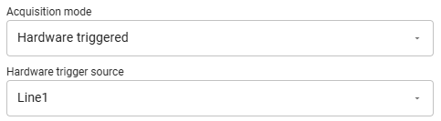
Connect the hardware trigger:
Physically connect your external trigger device to the selected input line on the camera.
Ensure the signal levels and timing are compatible with the camera's specifications (refer to the Basler camera hardware manual for supported voltage and timing ranges).
Verify trigger functionality:
- Test the setup by activating the external trigger and observing if the camera captures images as expected.