
Appearance
 Polygon
PolygonOverview
The Polygon node produces a user-defined polygon shape based on a list of coordinates. It's used to define areas of interest for detection and processing.
Use Polygon when:
- You need to specify a static spatial region for an analysis node.
- You want to define complex shapes for geometric operations or masking.
💡 Tip
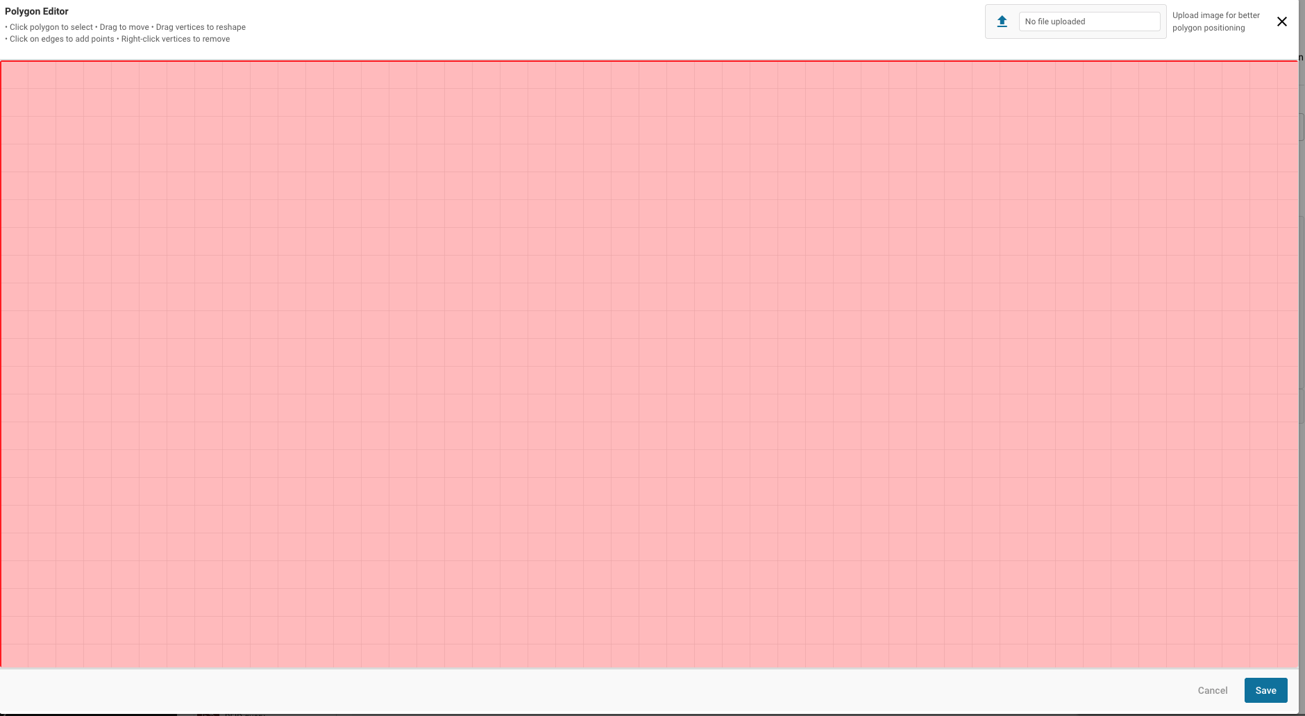
Use the interactive polygon widget to draw your shape directly on a reference image for precise placement.
Outputs
| Name | Type | Description |
|---|---|---|
| polygon | polygon | The defined set of polygon vertices. |
Parameters
| Parameter | Default | Valid values | Tunable |
|---|---|---|---|
| Polygon coordinates | unit square | list of at least 3 points | ❌ |
Polygon coordinates
A list of {"x", "y"} points that define the polygon vertices. Coordinates are normalized — expressed as fractions of the image dimensions where {"x": 0, "y": 0} is the top-left corner and {"x": 1, "y": 1} is the bottom-right corner. For example, {"x": 0.5, "y": 0.5} represents the center of the image.
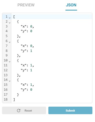
The default value is a unit square covering the full image: [{"x": 0, "y": 0}, {"x": 0, "y": 1}, {"x": 1, "y": 1}, {"x": 1, "y": 0}].
⚠️ Warning
The polygon must contain at least 3 points. Fewer points will cause a validation error.
Editing the polygon
The polygon parameter uses a visual widget with two editing modes:
JSON editor — Set coordinates numerically via a JSON structure.
Visual editor — Draw and adjust the polygon interactively on a preview image. Click the preview tab to open it.
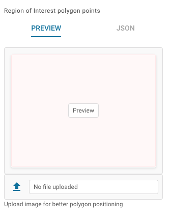
You can upload a reference image with the file uploader to position the polygon precisely over the area of interest. Click on the preview to open the interactive editor where you can drag individual points.
💡 Tip
Don't forget to save the polygon after editing — unsaved changes will be lost.
Example
Defining a surveillance zone
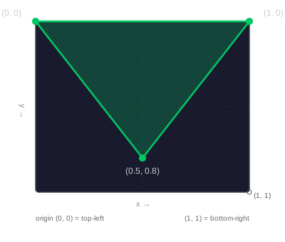
A user draws a triangular area over a specific entryway in a camera view. The Polygon node provides this shape to a detection node that only alerts on movement within that specific zone.
Configuration:
- Polygon coordinates:
[{"x": 0, "y": 0}, {"x": 1, "y": 0}, {"x": 0.5, "y": 0.8}]
Result: A triangular polygon object is output to the downstream flow.
Related links
Reference:
- Polygon Input — capture a dynamic polygon from an upstream process
- Polygon List — send a polygon to an external storage or system
- Region of Interest — define a region of interest specifically for image cropping